Pygletによる「手抜き」OpenGL入門
11. 三次元テクスチャー
11. 1 断面の表示
相分離現象とそのシミュレーション
異なる成分の物質が混じり合った系(二元系、例えば二種類以上の金属でできた合金や、二種類以上の高分子が混じり合ったポリマーブレンド系)では、 高い温度で均一に溶け合っている(固溶体を形成する)状態から、温度を下げていくと、組成の異なる金属や分子に分離することが知られている。 組成の異なる状態のそれぞれを、熱力学では物質の「相」と呼ぶことから、この現象は相分離と呼ばれている。 相分離を知ることは、役に立つ素材の開発にも役立つこともあって、熱統計物理学や素材科学の分野で長い研究の歴史がある。
異なる種類の原子や分子が一様に混じり合った状態を、ある変数(秩序変数と呼ばれている)$\phi$ が 0 である、と言い換えてみよう。 そうすると、高温状態では物体のあらゆる位置で$\phi = 0$ということになる。 AとBという二種類の物質が溶け合っている場合を考えてみると、温度を下げて相分離が生じると、Aを多く含む領域と、反対にBを多く含むような2つの相が出現する。 そして、2つの相の間には(それぞれが混じり合わないのだから)はっきりとした境界が形成される。 ここで、Aが多い状態を $\phi = 1$、Bが多い状態を$\phi = -1$と定義すると、空間は$\phi \approx 1$の領域と$\phi \approx -1$の領域に分かたれるわけだ。 2つの国が虫食い状に領土の奪い合いをした結果、地図が二色に色分けされているような状況である。
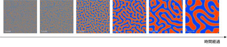
詳細には立ち入らないが、熱統計力学的な考察から、秩序変数の時間・空間的な変化の様子を数理モデル化することができ、 その中でも基本的なモデルとしてCahn–Hilliard方程式が知られている。 そして、この方程式を解くことで、物体の温度を急に下げたときにどのように内部の構造が変化するかについての知見が得られる。
2次元のCahn-Hilliardモデルのシミュレーション例。 最初は一様だった状態から徐々に赤色($\phi=1$)と青色($\phi=-1$) で示した相の領域(ドメイン)に分かれつつ、ドメイン自体も成長する。
ここでは、64✕64✕64の立方格子上でCahn–Hilliard方程式を実際に数値的に解いて、格子点での秩序変数の値を三次元データ化したファイルを あらかじめ用意しておいた(cahn–hilliard-model.npy。 データはNumPyのnpy形式で保存してあるので、
import numpy as np
phi = np.load("cahn–hilliard-model.npy")
のようにすれば、NumPyの三次元配列としてすぐに参照することができる。 ここで、$\phi$は-1,0,1の不連続な3つの値を取るわけではなく、連続的な値を取ることができて、1に近いほうがA相、-1に近いほうがB相(あるいはその逆)と解釈する。 ただし、このデータでは、A相の空間分布のみを表現するため、$\phi \lt 0$の点の値は0としている。
一次元や二次元のシステムならグラフや画像を使って結果を可視化することは容易であるが、このように、中身の詰まった3次元的な構造物を わかりやすく表現する方法は、 この例に限らず、CTやMRIによる画像診断や、レーザー共焦点顕微鏡等で得られる計測データの分析等、医療や研究の重要な課題と言える。
3次元テクスチャー
OpenGLには3次元のテクスチャーを扱う機能があって、3次元の格子状の各点(ボクセル)の色を与えておくと、 三角形等のプリミティブを描画する際に、頂点の間の色をテクスチャで自動的に補間させることができる。 2次元のテクスチャーの場合は図形の頂点と、テクスチャーの座標($u,v$)との対応関係を与えることで、面をテクスチャーを貼り付けてくれるものであったが、 3次元でも同様に、頂点とテクスチャー座標($u,v,w$)をセットで指定することで、面をテクスチャーで塗りつぶすことができるわけだ。 3次元のテクスチャは、横、縦、奥行き方向の3次元的の配列として与え、 座標は$u,v,w$がそれぞれ0から1の間の「単位立方体」の範囲で指定する。
Pygletで3次元テクスチャーを生成するには、まず3次元テクスチャーの奥行き毎の画像のリストを用意しておく。
ここで、それぞれの画像がすべて同じサイズである必要がある。
画像データのリストがimage_arrayで与えられているとすると、
texture_3d = pyglet.image.Texture3D.create_for_images(image_array, internalformat=GL_RED)
で3次元テクスチャーのオブジェクトが生成できる。
この場合、シミュレーションデータは$\phi$の値のみであるので、画像のフォーマットとしてGL_RED(0〜255の符号無し整数)を選択している。
次いで、二次元テクスチャーと同様に、
glActiveTexture(GL_TEXTURE0)
glBindTexture(texture_3d.target, texture_3d.id)
のようにしてバインドすることで、シェーダーから読み出すことができるようになる。
フラグメント・シェーダー側では
uniform sampler3D texture_3d;
のように sampler3D型のuniform変数を定義することで、
vec4 tex_color = texture(texture_3d, tex_coord);
のように テクスチャー座標(ここではtex_coordとする)と共にtexture()組み込み関数を呼び出すことで画素値を得ることができる。
切断面の生成
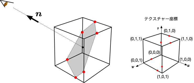
可視化の第一段階として、シミュレーションで得た3次元データを平面で切断し、切断面でのデータの値($\phi$)を表示してみることにしよう。
データは64 × 64 × 64 の配列で与えられているので、これを、原点を中心とし1辺の長さが2の立方体として表現してみる。 立方体は、ワールド座標系で、(-1,-1,-1)から(1,1,1)の領域を占めることになる。
法線ベクトルと、切断面に含まれる任意の点の座標が決まれば、切断平面を定義することができる。 そこでまず、切断平面と立方体の8つの辺との交点の座標を計算する。 交点は、平面の位置によって、0個(交差しない)の場合から、6個の場合まであり得る。 交点が求まったら、交点を結んでできる凸多角形の中心点と、隣り合う2つの頂点を使って三角形を生成する。 頂点座標から対応するテクスチャー画像に変換するのはこの場合は非常に簡単で、$(u, v, w) = (\frac{x + 1}{2}, \, \frac{y + 1}{2}, \, \frac{z + 1}{2})$ とすれば良い。
こうして、切断面を三角形のプリミティブによって描画することができるはずである。
以上のアイデアに基づいて、相分離のシミュレーションデータの断面を表示するコードを作成してみた例を以下に示す。 実行するには、データファイルをコードと同じディレクトリにダウンロードしておく必要がある。
視点(あるいはカメラの位置)は変数 x0,y0,z0で、切断面上の点は配列 point で指定しているので、値を変えて
見え方の変化を確認すると良い。
import pyglet
from pyglet.gl import *
from pyglet.math import Mat4, Vec3
from pyglet.graphics.shader import Shader, ShaderProgram
import numpy as np
import ctypes

vertex_source1 = '''#version 330 core
  in vec3 position;
  in vec3 tex_coords;

  out vec3 vertex_position;
  out vec3 vertex_tex_coord;

  uniform WindowBlock {
        mat4 projection;
        mat4 view;
  } window;

  uniform mat4 model ;

  void main(void)
  {
     mat4 modelview = window.view * model;
     vec4 pos = modelview * vec4(position, 1.0);
     gl_Position = window.projection * pos;
     vertex_tex_coord = tex_coords.xyz ;
  }
'''

fragment_source1 = '''#version 330 core
  in vec3 vertex_tex_coord;
  out vec4 final_colors;

  uniform sampler3D texture_3d;

  void main(void)
  {
     vec4 tex_color = texture(texture_3d, vertex_tex_coord);
     float alpha = tex_color.r ;
     if (alpha < 0.01) discard;
     final_colors = vec4(tex_color.r, tex_color.r, tex_color.r, alpha*0.5);
  }
'''

vertex_source2 = '''#version 330 core
  in vec3 position;

  uniform WindowBlock {
        mat4 projection;
        mat4 view;
  } window;

  uniform mat4 model ;

  void main(void)
  {
     mat4 modelview = window.view * model;
     vec4 pos = modelview * vec4(position, 1.0);
     gl_Position = window.projection * pos;
  }
'''

fragment_source2 = '''#version 330 core
  out vec4 final_colors ;
  void main(void)
  {
     final_colors = vec4(1.0, 0.0, 0.0, 1.0) ;
  }
'''

def load_npy_as_3d_texture(npy_file):
    image_stack = np.load(npy_file)
    image_array = []
    for i in range(image_stack.shape[0]):
        image_data = image_stack[i] * 255
        height, width = image_data.shape
        image_data = image_data.astype(np.uint8)
        image = pyglet.image.ImageData(width, height, 'R', image_data.tobytes())
        image_array.append(image)
    texture_3d = pyglet.image.Texture3D.create_for_images(image_array, internalformat=GL_RED)
    return texture_3d

def calculate_intersection(normal, point, edge):
    r0, r1 = np.array(edge[0]), np.array(edge[1])
    direction = r1 - r0
    denom = np.dot(normal, direction)

    if denom != 0:
        t = (np.dot(normal, point) - np.dot(normal, r0)) / denom
        if 0 <= t <= 1:
            return r0 + t * direction
    return None

def sort_intersections(intersections, normal):
    center = np.mean(intersections, axis=0)
    dr0 = (intersections[0] - center) / np.linalg.norm(intersections[0] - center)
    dr1 = np.cross(normal, dr0) / np.linalg.norm(np.cross(normal, dr0))

    angles = [np.arctan2(np.dot(dr0, (p - center) / np.linalg.norm(p - center)),
                         np.dot(dr1, (p - center) / np.linalg.norm(p - center)))
              for p in intersections]

    sorted_indices = np.argsort(angles)
    return intersections[sorted_indices], center

def generate_triangle_vertices(sorted_intersections, center):
    vertices = []
    nisect = len(sorted_intersections)

    for i in range(nisect):
        next_i = (i + 1) % nisect
        vertices.extend(sorted_intersections[i].tolist() +
                        center.tolist() +
                        sorted_intersections[next_i].tolist())

    return vertices

def gen_triangles(normal, point):
    edges = [
        [[-1, -1, -1], [1, -1, -1]], [[-1, -1, -1], [-1, 1, -1]], [[-1, -1, -1], [-1, -1, 1]],
        [[1, 1, 1], [-1, 1, 1]], [[1, 1, 1], [1, -1, 1]], [[1, 1, 1], [1, 1, -1]],
        [[-1, 1, 1], [-1, -1, 1]], [[-1, 1, 1], [-1, 1, -1]], [[1, -1, 1], [-1, -1, 1]],
        [[1, -1, 1], [1, -1, -1]], [[1, 1, -1], [1, -1, -1]], [[1, 1, -1], [-1, 1, -1]]
    ]

    intersections = [calculate_intersection(normal, point, edge) for edge in edges]
    intersections = [pt for pt in intersections if pt is not None]

    if not intersections:
        return []

    sorted_intersections, center = sort_intersections(np.array(intersections), normal)
    vertices = generate_triangle_vertices(sorted_intersections, center)

    return vertices

window = pyglet.window.Window(800, 600, "3D Texture Example")

batch1 = pyglet.graphics.Batch()
vert_shader1 = Shader(vertex_source1, 'vertex')
frag_shader1 = Shader(fragment_source1, 'fragment')
shader1 = ShaderProgram(vert_shader1, frag_shader1)

npy_file = 'cahn–hilliard-model.npy'
texture = load_npy_as_3d_texture(npy_file)

glClearColor(0.3, 0.3, 0.5, 1.0)
glEnable(GL_DEPTH_TEST)

glActiveTexture(GL_TEXTURE0)
glBindTexture(texture.target, texture.id)

# camera position in the world coordinate
x0 = 4
y0 = 3
z0 = 6

# the vector perpendicular to the intersecting plane
normal = np.array([x0, y0, z0], dtype='float')
normal /= np.linalg.norm(normal)
# the coordinates of a point contained within the intersecting plane
point = np.array([0,0,0.0],dtype='float')

vertices = gen_triangles(normal, point)
tex_coords = (np.array(vertices) + 1) * 0.5

vertex_list = shader1.vertex_list(len(vertices) // 3, GL_TRIANGLES, batch=batch1)
vertex_list.position[:] = vertices
vertex_list.tex_coords[:] = tex_coords

# draw the bounding cube
vert_shader2 = Shader(vertex_source2, 'vertex')
frag_shader2 = Shader(fragment_source2, 'fragment')
shader2 = ShaderProgram(vert_shader2, frag_shader2)
batch2 = pyglet.graphics.Batch()
cube = shader2.vertex_list(24, GL_LINES,
                           position=('f',(-1, -1, -1, 1, -1, -1,    -1, -1, -1, -1, 1, -1,    -1, -1, -1, -1, -1, 1,
                                          1, 1, 1, -1, 1, 1,    1, 1, 1, 1, -1, 1,    1, 1, 1, 1, 1, -1,
                                          -1, 1, 1, -1, -1, 1,    -1, 1, 1, -1, 1, -1,    1, -1, 1, -1, -1, 1,
                                          1, -1, 1, 1, -1, -1,    1, 1, -1, 1, -1, -1, 1,    1, -1, -1, 1, -1)),
                           batch=batch2)

time=0
def update(dt):
    global time
    time = time + dt
    model_mat = Mat4.from_rotation(time,Vec3(0,1,0))
    shader1['model']= model_mat
    shader2['model']= model_mat

@window.event
def on_draw():
    ratio = window.height/window.width
    window.clear()
    window.viewport = (0, 0, window.width, window.height)
    window.projection = Mat4.orthogonal_projection(-2,2,-2*ratio,2*ratio,-10,20)
    batch1.draw() # intersection
    batch2.draw() # wireframe

window.view = Mat4.look_at(position=Vec3(x0,y0,z0), target=Vec3(0,0,0), up=Vec3(0,1,0))
pyglet.clock.schedule_interval(update,1/30)
pyglet.app.run()
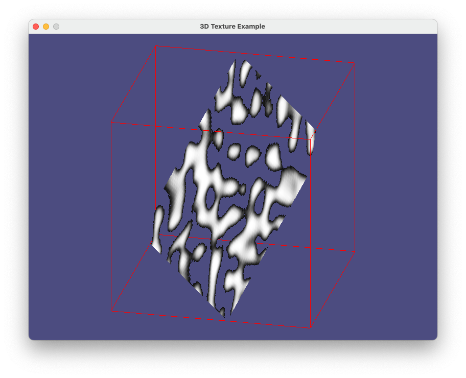
prog-11-1.pyの実行画面のスナップショット

11. 2 ボリューム表現
アルファ・ブレンディングによる方法
切断面のみでは構造が把握しにくい場合も多いが、さりとて中身の詰まった物体をそのまま描画しようとすると、表面部分しか見ることができない。 そこで、物体の内部も透けて表示されるような手法(ボリュームレンダリングと呼ばれる)がいくつか開発されている。 ここでは、最もシンプルな、透過度(アルファ値)をブレンドする方法を試してみよう。
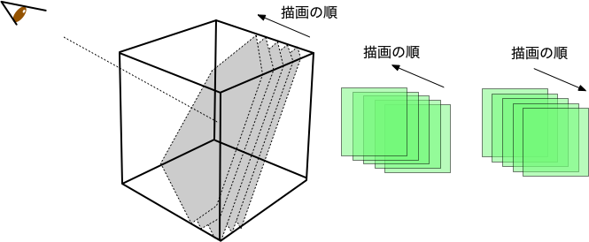
基本的なアイデアはとてもシンプルで、切断面を沢山用意しておいて、各切断面からの画素をブレンドしながら重ね合わせればよい。 画素の透明度を適切に調整することで、背後の画素もある程度透けて見えるはずである。 そのため、描画に先立って
glBlendFunc(GL_SRC_ALPHA, GL_ONE_MINUS_SRC_ALPHA)
glEnable(GL_BLEND)
を呼び出してブレンディングを有効化しておく。
OpenGLのアルファ・ブレンディングは、描画を行った順番に行われる点に注意したい。 新たに描画する画素値を $p$、すでにそのピクセルに書き込まれていた画素値を $q$ とすると、アルファ・ブレンディングでは $$ \alpha \, p + (1-\alpha)\,q $$ が新たな画素として描画される。$\alpha = 1$であれば古い画素は完全に上書きされ、$\alpha=0$ならば以前の画素値そのままとなる。 そのため、物体の内部がある程度透けて見えるようにするためには、カメラ(視点)から奥側のデータから順に描画を行わないと、濃淡や色合いがおかしなことになってしまう。
多数の切断面の作成
すでに、前の節の例(prog-11-1.py)で、物体から視点方向を法線とすと切断面を生成するコード(gen_triangles()関数)は作成済みなので、
これを用いて、視点から遠い位置から手前方向の順に切断面を生成する関数(gen_slices())を追加することにしよう。
加えて、切断面の生成コードはワールド座標で立方体の頂点が(-1,-1,-1)・・・(1,1,1)に位置することを前提にしているので、 物体の位置が(モデル変換によって)変更されてしまうと正しく計算を行うことができない。 そのため、モデル変換行列の逆行列を計算し、カメラ位置を補正しながら、切断面の計算を行う方針とした。
ただし、描画の都度、多数の切断面の頂点座標を計算し直しているので、甚だ効率が悪い(こちらも参照のこと)。
アルファ・ブレンディングを行う際には、視点の奥側から順に描画する必要がある。 全く同じ配置の図形でも、描画順によって、前後関係が違って見える。
以上のアイデアをもとに、prog-11-1.pyを修正してみたコードを以下に示す。 フラグメント・シェーダーの
final_colors = vec4(tex_color.r, tex_color.r, tex_color.r, alpha*0.5);
の箇所が画素の透明度を決めているので、例えば、alpha*0.5のところをalpha*0.05等にすると、
より奥手側が透けて見えることになる。
import pyglet
from pyglet.gl import *
from pyglet.math import Mat4, Vec3, Vec4  ##### Vec4を追加
from pyglet.graphics.shader import Shader, ShaderProgram
import numpy as np
import ctypes

##
## シェーダーの定義から、切断面を生成する関数のところまで prog-11-1.pyと同じ
##
##

window = pyglet.window.Window(800, 600, "3D Texture Example")

batch1 = pyglet.graphics.Batch()
vert_shader1 = Shader(vertex_source1, 'vertex')
frag_shader1 = Shader(fragment_source1, 'fragment')
shader1 = ShaderProgram(vert_shader1, frag_shader1)

npy_file = 'cahn–hilliard-model.npy'
texture = load_npy_as_3d_texture(npy_file)

glClearColor(0.3, 0.3, 0.5, 1.0)
glEnable(GL_DEPTH_TEST)
glBlendFunc(GL_SRC_ALPHA, GL_ONE_MINUS_SRC_ALPHA)   #####
glEnable(GL_BLEND)                                  #####
glActiveTexture(GL_TEXTURE0)
glBindTexture(texture.target, texture.id)

def gen_slices(x0, y0, z0, batch):
    normal = np.array([x0, y0, z0], dtype='float')
    normal /= np.linalg.norm(normal)

    vertices = []
    tex_coords = []
    d_values = np.linspace(-np.sqrt(3), np.sqrt(3), 256)

    for d in d_values:
        point = d * normal
        triangles = gen_triangles(normal, point)
        if triangles:
            vertices.extend(triangles)
            tex_coords.extend((np.array(triangles) + 1) * 0.5)

    vertex_list = shader1.vertex_list(len(vertices) // 3, GL_TRIANGLES, batch=batch)
    vertex_list.position[:] = vertices
    vertex_list.tex_coords[:] = tex_coords

    return vertex_list

# camera position
x0 = 0
y0 = 10
z0 = 10
camera_pos = Vec3(x0,y0,z0)
# initial slices
vertex_list = gen_slices(x0,y0,z0,batch1)

# draw the bounding cube
vert_shader2 = Shader(vertex_source2, 'vertex')
frag_shader2 = Shader(fragment_source2, 'fragment')
shader2 = ShaderProgram(vert_shader2, frag_shader2)
batch2 = pyglet.graphics.Batch()
cube = shader2.vertex_list(24, GL_LINES,
                           position=('f',(-1, -1, -1, 1, -1, -1,    -1, -1, -1, -1, 1, -1,    -1, -1, -1, -1, -1, 1,
                                          1, 1, 1, -1, 1, 1,    1, 1, 1, 1, -1, 1,    1, 1, 1, 1, 1, -1,
                                          -1, 1, 1, -1, -1, 1,    -1, 1, 1, -1, 1, -1,    1, -1, 1, -1, -1, 1,
                                          1, -1, 1, 1, -1, -1,    1, 1, -1, 1, -1, -1, 1,    1, -1, -1, 1, -1)),
                           batch=batch2)

time=0
model_mat = Mat4()
def update(dt):
    global vertex_list ,time, model_mat
    time = time + dt
    model_mat = Mat4.from_rotation(time*0.1,Vec3(0,1,0))
    inv_pos = model_mat.__invert__() @ Vec4(camera_pos.x, camera_pos.y, camera_pos.z, 1.0)
    # regenerate slice
    vertex_list.delete()
    vertex_list = gen_slices(inv_pos.x, inv_pos.y, inv_pos.z, batch1)


@window.event
def on_draw():
    window.clear()
    ratio = window.height/window.width
    window.viewport = (0, 0, window.width, window.height)
    window.projection = Mat4.orthogonal_projection(-2,2,-2*ratio,2*ratio,-10,20)
    shader1['model']= model_mat
    shader2['model']= model_mat
    batch1.draw()
    batch2.draw()

window.view = Mat4.look_at(position=camera_pos, target=Vec3(0,0,0), up=Vec3(0,1,0))
pyglet.clock.schedule_interval(update,1/30)
pyglet.app.run()
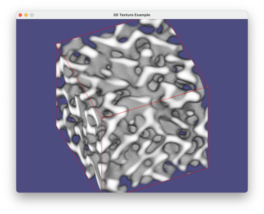
prog-11-2.pyの実行画面のスナップショット
 解説: 生成AIによるシェーダーコードの生成
prog-11-2.pyでは、切断面のテクスチャー座標の計算をCPU側のPythonコードで行っているため、レンダリングの都度それらを計算すると、どうしても時間を要してしまい、
パソコンによっては表示がカクついてしまうかもしれない。
そこで、座標計算を行っているPython関数(calculate_intersection(), csort_intersections(), generate_triangle_vertices(), gen_triangles() )のコードを
以下は、法線ベクトルと点の座標を与えると、その点を通る平面と立方体の辺との交点を計算し、交点を頂点とする多角形を構成する三角形のプリミティブの頂点座標を求めるPythonの関数です。 これをGLSLのジオメトリシェーダー用のコードに変換してください。
というプロンプトと共にChatGPTに与えたところ、以下の修正点を除いて、ほぼ完全なシェーダーコードが生成された。
- 当初
layout (triangles) in;となっていた箇所をlayout (points) in;に修正 - シェーダーのバージョンを450用から330用に修正
- 2次元配列(配列の配列)を用いていた箇所があったので、すべて1次元の配列を使うように修正
ChatGPTが生成したコードに、頂点シェーダーとフラグメント・シェーダーとのデータの受け渡しなどの若干の手直しを加えてできたジオメトリ・シェーダーが以下のとおりである:
ChatGPTが(ほとんど)生成したジオメトリ・シェーダー
#version 330 core
layout(points) in;
layout(triangle_strip, max_vertices = 32) out;

 in VS_OUT {
      vec3 position;
      vec3 normal;
 } gs_in[];

 out vec3 geom_tex_coord;

 uniform mat4 model;

 uniform WindowBlock
 {
      mat4 projection;
      mat4 view;
 } window;

  vec3 calculate_intersection(vec3 normal, vec3 point, vec3 r0, vec3 r1) {
      vec3 direction = r1 - r0;
      float denom = dot(normal, direction);

      if (denom != 0.0) {
          float t = (dot(normal, point) - dot(normal, r0)) / denom;
          if (t >= 0.0 && t <= 1.0) {
              return r0 + t * direction;
          }
      }
      return vec3(0.0);
  }

  void sort_intersections(inout vec3 intersections[12], int count, vec3 normal) {
      vec3 center = vec3(0.0);
      for (int i = 0; i < count; i++) {
          center += intersections[i];
      }
      center /= float(count);

      vec3 dr0 = normalize(intersections[0] - center);
      vec3 dr1 = normalize(cross(normal, dr0));

      float angles[12];
      for (int i = 0; i < count; i++) {
          vec3 p = normalize(intersections[i] - center);
          angles[i] = atan(dot(dr0, p), dot(dr1, p));
      }

      for (int i = 0; i < count; i++) {
          for (int j = 0; j < count - 1 - i; j++) {
              if (angles[j] > angles[j + 1]) {
                  float tempAngle = angles[j];
                  vec3 tempVec = intersections[j];
                  angles[j] = angles[j + 1];
                  intersections[j] = intersections[j + 1];
                  angles[j + 1] = tempAngle;
                  intersections[j + 1] = tempVec;
              }
          }
      }
  }

  void main() {
      vec3 cube_edges[24] = vec3[24](
          vec3(-1, -1, -1), vec3(1, -1, -1),
          vec3(-1, -1, -1), vec3(-1, 1, -1),
          vec3(-1, -1, -1), vec3(-1, -1, 1),
          vec3(1, 1, 1), vec3(-1, 1, 1),
          vec3(1, 1, 1), vec3(1, -1, 1),
          vec3(1, 1, 1), vec3(1, 1, -1),
          vec3(-1, 1, 1), vec3(-1, -1, 1),
          vec3(-1, 1, 1), vec3(-1, 1, -1),
          vec3(1, -1, 1), vec3(-1, -1, 1),
          vec3(1, -1, 1), vec3(1, -1, -1),
          vec3(1, 1, -1), vec3(1, -1, -1),
          vec3(1, 1, -1), vec3(-1, 1, -1)
      );

      vec3 intersections[12];
      int nIntersections = 0;

      for (int i = 0; i < 12; i++) {
          vec3 intersection = calculate_intersection(gs_in[0].normal, gs_in[0].position, cube_edges[2 * i], cube_edges[2 * i + 1]);
          if (intersection != vec3(0.0)) {
              intersections[nIntersections++] = intersection;
          }
      }

      mat4 modelview = window.view * model;
      vec4 pos = modelview * vec4(gs_in[0].position, 1.0);

      if (nIntersections > 2) {
          sort_intersections(intersections, nIntersections, gs_in[0].normal);
          vec3 center = vec3(0.0);
          for (int i = 0; i < nIntersections; i++) {
              center += intersections[i];
          }
          center /= float(nIntersections);

          for (int i = 0; i < nIntersections; i++) {
              int next_i = (i + 1) % nIntersections;

              gl_Position = window.projection * modelview * vec4(intersections[i], 1.0);
              geom_tex_coord = (vec3(intersections[i]) + vec3(1,1,1)) / 2 ;
              EmitVertex();

              gl_Position = window.projection * modelview * vec4(center, 1.0);
              geom_tex_coord = (vec3(center) + vec3(1,1,1)) / 2 ;
              EmitVertex();

              gl_Position = window.projection * modelview * vec4(intersections[next_i], 1.0);
              geom_tex_coord = (vec3(intersections[next_i]) + vec3(1,1,1)) / 2 ;
              EmitVertex();

              EndPrimitive();
          }
      }
  }
以上を組み込んだPygletコードの全体が prog-11-2-gs.py である。
もし研究開発などで同じ作業を求められたとすると、ChatGPTを使うことでかなりの時短になったことは間違いなく、 単純なコードの変換作業などでは、もう人間の出番はなくなりつつあるのかもしれない・・・。
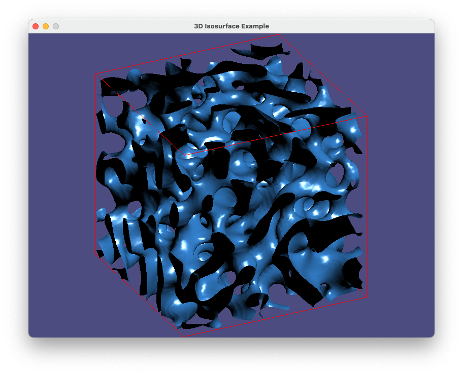
11. 3 等高面による表示
Skimageを用いた等高面の生成
3次元データを可視化する方法として、等高面の表示もよく使われるので、OpenGLのテクスチャーとは関係ないが、ここで触れておきたい。
このパートでサンプルに用いているデータは、3次元の格子点上で値が与えられているので、補間を行うことで、等高面(isosurface)を生成することができる。 等高面の生成アルゴリズムについてはここでは触れず、scikit-imageに実装されている マーチングキューブ法を用いたライブラリ関数skimage.measure.marching_cubes()を用いることにする。
もしまだならば、scikit-image をインストールしておく。
pip install scikit-image
marching_cubes()関数を以下のように呼び出すと、レベル値で指定した等高面に対応する三角形の頂点データを得ることができる。
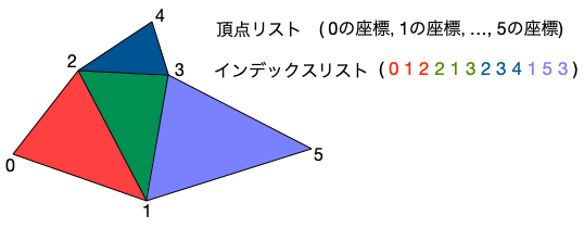
頂点のリスト, 法線のリスト, 頂点のインデックスリスト, 値のリスト = skimage.measure.marching_cubes(3次元配列, レベル値)
頂点のリストは複数の三角形の頂点で共有される(ひとつの頂点から複数のエッジが出ている)ので、どの頂点の組で三角形が構成されるのかを
頂点のインデックスリストで指定している。例えば、インデックスのリストに(3つずつ組の)2,1,3 の並びがあれば、
頂点リストの2,1,3番目の座標でひとつの三角形が構成される、といった具合である。
インデックス化された頂点リスト
こうしたインデックス化された頂点リストを扱う機能がPygletには備わっており、OpenGLの描画を行う際には
頂点リストオブジェクト = pyglet.graphics.ShaderProgram.vertex_list_indexed(頂点の数, プリミティブの種類, 頂点のインデックスリスト)
をそのまま用いることができる。
以下のコードの例では、関数 load_npy_and_gen_model() の中で、等高面データの生成と、
それを用いたOpenGLの頂点リストの生成、マテリアルパラメータを含むモデルの生成までを、ほんの20行ほどのコードで行っている。
マテリアル表現については、パート3のコードをほぼそのまま援用しているが、 三角形の裏面で光源からの反射を止めるために、フラグメント・シェーダーに
if (dot(normal, light_dir)<0) spec=0.0 ;
の1行が追加されている点だけは違っている。
import pyglet
from pyglet.gl import *
from pyglet.math import Mat4, Vec3, Vec4
from pyglet.graphics.shader import Shader, ShaderProgram
import numpy as np
import ctypes
from skimage import measure

vertex_source1 = '''#version 330 core
    in vec3 position;
    in vec3 normals;
    in vec4 diffuse_colors;
    in vec4 ambient_colors;
    in vec4 specular_colors;
    in vec4 emission_colors;
    in float shininess;

    out vec4 vertex_diffuse;
    out vec4 vertex_ambient;
    out vec4 vertex_specular;
    out vec4 vertex_emission;
    out float vertex_shininess;
    out vec3 vertex_normals;
    out vec3 vertex_position;

    uniform WindowBlock
    {
        mat4 projection;
        mat4 view;
    } window;

    uniform mat4 model;

    void main()
    {
        mat4 modelview = window.view * model;
        vec4 pos = modelview * vec4(position, 1.0);
        gl_Position = window.projection * pos;
        mat3 normal_matrix = transpose(inverse(mat3(modelview)));
        vertex_position = pos.xyz;
        vertex_diffuse = diffuse_colors;
        vertex_ambient = ambient_colors;
        vertex_specular = specular_colors;
        vertex_emission = emission_colors;
        vertex_shininess = shininess;
        vertex_normals = normal_matrix * normals;
    }
'''

fragment_source1 = '''#version 330 core
    in vec4 vertex_diffuse;
    in vec4 vertex_ambient;
    in vec4 vertex_specular;
    in vec4 vertex_emission;
    in float vertex_shininess;
    in vec3 vertex_normals;
    in vec3 vertex_position;
    out vec4 final_colors;

    uniform vec3 light_position;
    uniform vec4 light_color;

    void main()
    {
        vec3 normal = normalize(vertex_normals);
        vec3 light_dir = normalize(light_position - vertex_position);
        vec3 refrect_dir = reflect(-light_dir, normal);
        vec3 view_dir = -normalize(vertex_position);
        float spec = pow(max(dot(view_dir, refrect_dir), 0.0), vertex_shininess);
        float diff = max(dot(normal, light_dir), 0.0);
        if (dot(normal, light_dir)<0) spec=0.0 ;

        final_colors = vertex_ambient * light_color
                     + vertex_diffuse * diff
                     + vertex_specular * spec * light_color
                     + vertex_emission ;
    }
'''
vertex_source2 = '''#version 330 core
   in vec3 position;

   uniform WindowBlock {
        mat4 projection;
        mat4 view;
   } window;

   uniform mat4 model ;

   void main(void)
   {
     mat4 modelview = window.view * model;
     vec4 pos = modelview * vec4(position, 1.0);
     gl_Position = window.projection * pos;
   }
'''

fragment_source2 = '''#version 330 core
   out vec4 final_colors ;
   void main(void)
   {
     final_colors = vec4(1.0, 0.0, 0.0, 1.0) ;
   }
'''

class MyMaterialGroup(pyglet.model.BaseMaterialGroup):
    def __init__(self, material:pyglet.model.Material, program: pyglet.graphics.shader.ShaderProgram, \
             order:int=0, parent: pyglet.graphics.Group = None):
        super().__init__(material, program, order, parent)

    def set_state(self) -> None:
        self.program.use()
        self.program['model'] = self.matrix

    def __hash__(self) -> int:
        return hash((self.program, self.order, self.parent))
    def __eq__(self, other) -> bool:
        return (self.__class__ is other.__class__ and
            self.material == other.material and
            self.matrix == other.matrix and
            self.program == other.program and
            self.order == other.order and
            self.parent == other.parent)

window = pyglet.window.Window(800, 600, "3D Isosurface Example")

batch1 = pyglet.graphics.Batch()
vert_shader1 = Shader(vertex_source1, 'vertex')
frag_shader1 = Shader(fragment_source1, 'fragment')
shader1 = ShaderProgram(vert_shader1, frag_shader1)

glClearColor(0.3, 0.3, 0.5, 1.0)
glEnable(GL_DEPTH_TEST)

def load_npy_and_gen_model(npy_file, iso_level, shader, batch):
    data3d = np.load(npy_file)
    vertices, faces, normals, values = measure.marching_cubes(data3d, level=iso_level)

    xsiz,ysiz,zsiz = data3d.shape
    scales = np.array([2/xsiz,2/ysiz,2/zsiz])

    vertices = vertices * scales[:]
    vertices = vertices.flatten() - 1
    normals  = normals * scales[:]
    normals = normals.flatten()

    indices = faces.flatten()

    diffuse = (0.2,0.5,0.8,1)
    ambient = (0,0,0,1)
    specular = (1,1,1,1)
    emission = (0,0,0,1)
    shininess = 20

    material = pyglet.model.codecs.base.SimpleMaterial("custom", diffuse, ambient, specular, emission, shininess)
    group = MyMaterialGroup(material=material, program=shader)

    vertex_list = shader.vertex_list_indexed(len(vertices)//3, GL_TRIANGLES, indices, batch=batch, group=group)
    vertex_list.position[:] = vertices
    vertex_list.normals[:] = normals
    vertex_list.diffuse_colors[:] = material.diffuse * (len(vertices)//3)
    vertex_list.ambient_colors[:] = material.ambient * (len(vertices)//3)
    vertex_list.specular_colors[:] = material.specular * (len(vertices)//3)
    vertex_list.emission_colors[:] = material.emission * (len(vertices)//3)
    vertex_list.shininess[:] = [material.shininess] * (len(vertices)//3)

    return pyglet.model.Model(vertex_lists=[vertex_list], groups=[group], batch=batch)

npy_file = 'cahn–hilliard-model.npy'
iso_model = load_npy_and_gen_model(npy_file, 0.5, shader1, batch1)

# draw a cube
vert_shader2 = Shader(vertex_source2, 'vertex')
frag_shader2 = Shader(fragment_source2, 'fragment')
shader2 = ShaderProgram(vert_shader2, frag_shader2)
batch2 = pyglet.graphics.Batch()
cube = shader2.vertex_list(24, GL_LINES,
                           position=('f',(-1, -1, -1, 1, -1, -1,    -1, -1, -1, -1, 1, -1,    -1, -1, -1, -1, -1, 1,
                                          1, 1, 1, -1, 1, 1,    1, 1, 1, 1, -1, 1,    1, 1, 1, 1, 1, -1,
                                          -1, 1, 1, -1, -1, 1,    -1, 1, 1, -1, 1, -1,    1, -1, 1, -1, -1, 1,
                                          1, -1, 1, 1, -1, -1,    1, 1, -1, 1, -1, -1, 1,    1, -1, -1, 1, -1)),
                           batch=batch2)

time=0
model_mat = Mat4()
def update(dt):
    global time, model_mat
    time = time + dt
    model_mat = Mat4.from_rotation(time*0.1,Vec3(0,1,0))

@window.event
def on_draw():
    window.clear()
    ratio = window.height/window.width
    window.viewport = (0, 0, window.width, window.height)
    window.projection = Mat4.orthogonal_projection(-2,2,-2*ratio,2*ratio,-10,20)
    shader1['light_color'] = Vec4(1,1,1,1)
    shader1['light_position'] = Vec3(10,10,10)
    iso_model.matrix= model_mat
    shader2['model']= model_mat
    batch1.draw()
    batch2.draw()


window.view = Mat4.look_at(position=Vec3(0,5,10), target=Vec3(0,0,0), up=Vec3(0,1,0))
pyglet.clock.schedule_interval(update,1/30)
pyglet.app.run()
prog-11-3.pyの実行画面のスナップショット