Pygletによる「手抜き」OpenGL入門
7. テクスチャ
7.1 書き割り式の物体表現
コンピュータグラフィックスで物体表面のパターンや質感を表現する際に、一般に用いられるのが、3次元物体の表面に2次元的な画像を「貼り付ける」方法だ。 プラモデルの表面にデカールを貼りつけるようなイメージである。そして、物体表面に貼られた画像のことをテクスチャと呼んでいる。
あらかじめ二次元画像をJPEGやPNGファイルとして用意しておき、画像上の位置と物体の頂点の位置との対応関係を与えてやると、OpenGLは自動的に画像を貼り付けてくれる。 その対応関係を表すために、矩形の画像の左下を(0,0)、右上を(1,1)とする座標系(テクスチャ座標)を用いる。 テクスチャを扱う際に、座標変数に$u$と$v$をよく使うことから、uv座標と呼ぶこともある。 そして、物体の何番目の頂点はテクスチャ座標これこれ、・・・、といった情報を頂点リストに加えておけばよい。
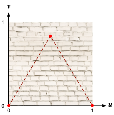
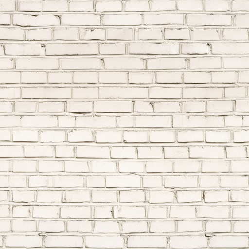
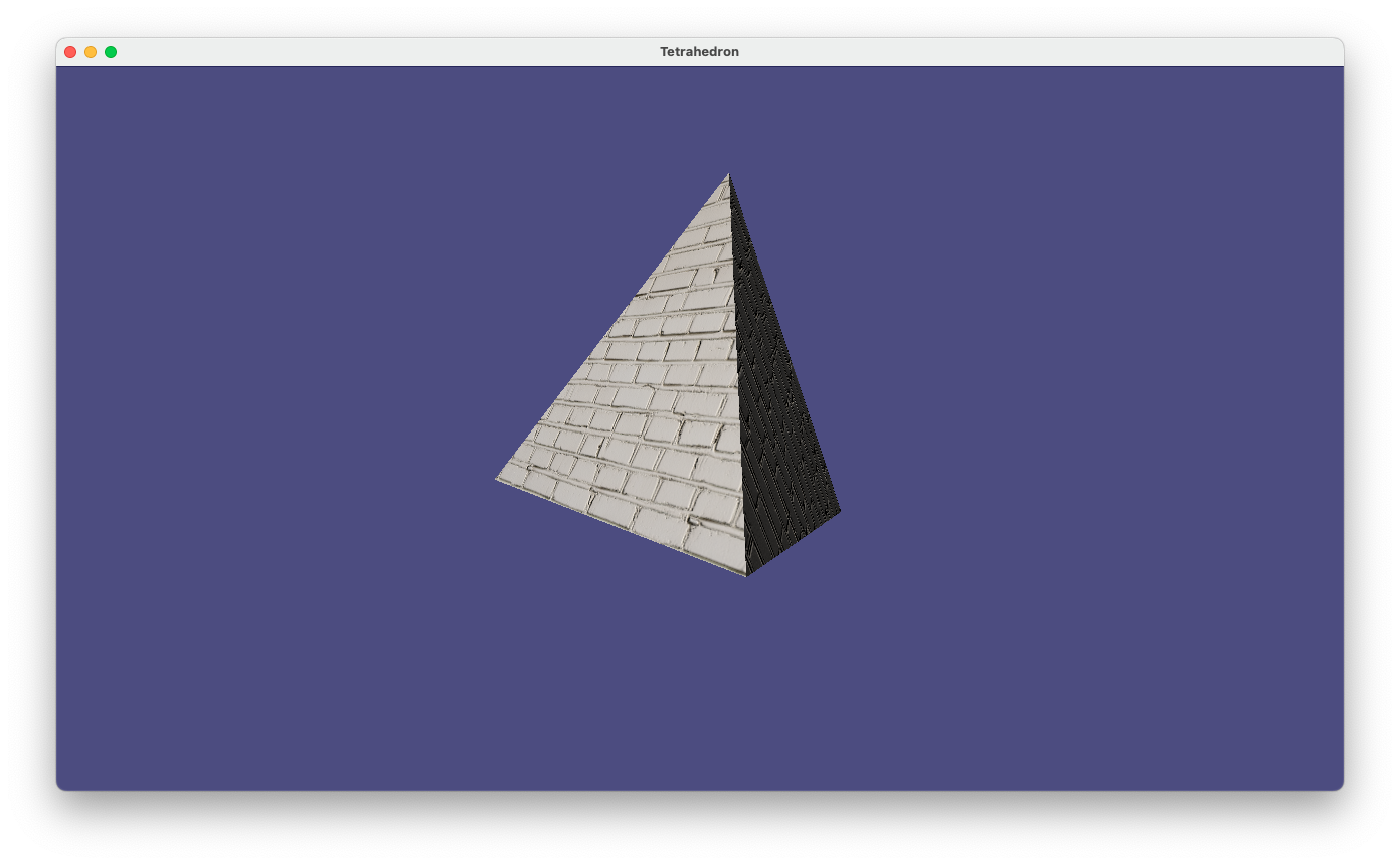
ここでは正四面体の三角形の各面に、下図のようなレンガのようなパターンを貼り付けてみる。 三角形の各頂点には、テクスチャ座標で$(0,0), (1,0), (1/2, \sqrt{3}/2)$ を対応させる。 言うまでもなく、$\sqrt{3}/2$は一辺の長さが1の正三角形の高さである。
画像ファイルを読み込んで、テクスチャ情報として登録するには、Pygletの機能を使って
brick_wall = pyglet.image.load('brick-wall.png')
texture = brick_wall.get_texture()
のようにするだけで済む。
prog-5-3.pyのコードを少し変更して、正四面体の各面にレンガのテクスチャを貼り付けるようにしたコードの例を以下に示す。
変更箇所は案外と僅かで、コード中に ##### で示しておいた。
import numpy as np
import math
import pyglet
from pyglet.gl import *
from pyglet.math import Mat4, Vec3
from pyglet.graphics.shader import Shader, ShaderProgram

# シェーダー
# Vertex shader
vertex_source = """#version 330 core
    in vec3 position;
    in vec3 normals;
    in vec4 colors;
    in vec2 tex_coords;       // #####

    out vec4 vertex_colors;
    out vec3 vertex_normals;
    out vec3 vertex_position;
    out vec2 texture_coords;  // #####

    uniform WindowBlock
    {
        mat4 projection;
        mat4 view;
    } window;

    uniform mat4 model;

    void main()
    {
        mat4 modelview = window.view * model;
        vec4 pos = modelview * vec4(position, 1.0);
        gl_Position = window.projection * pos;
        mat3 normal_matrix = transpose(inverse(mat3(modelview)));
        vertex_position = pos.xyz;
        vertex_colors = colors;
        vertex_normals = normal_matrix * normals;
        texture_coords = tex_coords;
    }
"""

fragment_source = """#version 330 core
    in vec4 vertex_colors;
    in vec3 vertex_normals;
    in vec3 vertex_position;
    in vec2 texture_coords;  // #####
    out vec4 final_colors;

    uniform vec3 light_position;
    uniform sampler2D texture_2d;  // #####

    void main()
    {
        vec3 normal = normalize(vertex_normals);
        vec3 light_dir = normalize(light_position - vertex_position);
        float diff = max(dot(normal, light_dir), 0.0);
        final_colors = (texture(texture_2d, texture_coords) * vertex_colors) * diff * 1.2;  // #####
    }
"""

window = pyglet.window.Window(width=1280, height=720, resizable=True)
window.set_caption('Tetrahedron')

batch = pyglet.graphics.Batch()
vert_shader = Shader(vertex_source, 'vertex')
frag_shader = Shader(fragment_source, 'fragment')
shader = ShaderProgram(vert_shader, frag_shader)

brick_wall = pyglet.image.load('brick-wall.png')  #####
texture = brick_wall.get_texture()                #####

time=0
def update(dt):
    global time
    time += dt

@window.event
def on_draw():
    window.clear()
    shader['model']=Mat4.from_rotation(time,Vec3(1,0,0)) @ Mat4.from_rotation(time/3,Vec3(0,1,0))
    shader['light_position']=Vec3(-5,5,20)
    batch.draw()

@window.event
def on_resize(width, height):
    window.viewport = (0, 0, width, height)
    window.projection = Mat4.perspective_projection(window.aspect_ratio, z_near=0.1, z_far=255, fov=60)
    return pyglet.event.EVENT_HANDLED

def setup():
    glClearColor(0.3, 0.3, 0.5, 1.0)
    glEnable(GL_DEPTH_TEST)
    glEnable(GL_CULL_FACE)
    glActiveTexture(GL_TEXTURE0)               #####
    glBindTexture(texture.target, texture.id)  #####
    on_resize(*window.size)

def tetrahedron(shader, batch):
    vpos = [np.array((+1,0,-1/math.sqrt(2))), np.array((-1,0,-1/math.sqrt(2))),
            np.array((0,1,1/math.sqrt(2))), np.array((0,-1,1/math.sqrt(2)))]
    indices = [(0,1,2),(0,3,1),(0,2,3),(1,3,2)]
    normals = []
    vertices = []
    tex_coords = []  ## <===

    for n in range(4):
        i = indices[n][0]
        j = indices[n][1]
        k = indices[n][2]
        vertices.extend([vpos[i],vpos[j],vpos[k]])
        u = vpos[j] - vpos[i]
        v = vpos[k] - vpos[i]
        n = np.cross(u,v)
        n = n/np.linalg.norm(n)
        normals.extend([n,n,n])
        tex_coords.extend([0, 0, 1, 0, 0.5, math.sqrt(3)/2])  #####

    vertices = np.concatenate(vertices).tolist()
    normals = np.concatenate(normals).tolist()

    vertex_list = shader.vertex_list(len(vertices)//3, GL_TRIANGLES, batch=batch)
    vertex_list.position[:] = vertices
    vertex_list.normals[:] = normals
    vertex_list.colors[:] = (1.0,1.0,1.0,1.0) * (len(vertices)//3)
    vertex_list.tex_coords[:] = tex_coords   #####

    return vertex_list

# OpenGLの初期設定
setup()

# 正四面体モデルを生成
th_vertex_list = tetrahedron(shader,batch)

# 視点を設定
window.view = Mat4.look_at(position=Vec3(0,0,3), target=Vec3(0,0,0), up=Vec3(0,1,0))

pyglet.clock.schedule_interval(update,1/60)
pyglet.app.run()
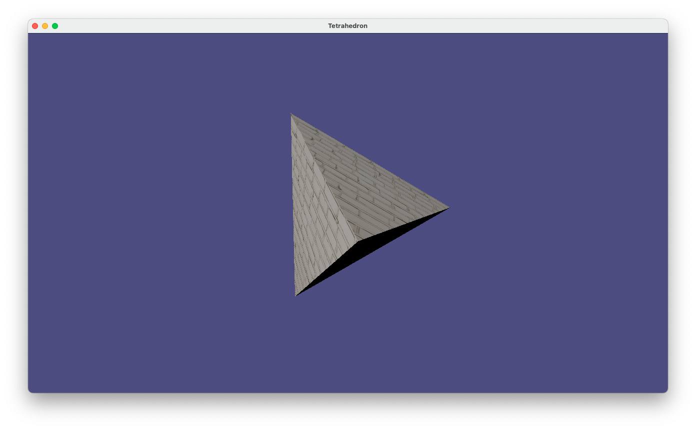
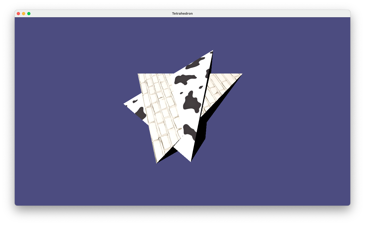
prog-7-1.pyの実行画面
シェーダープログラムの変更箇所
頂点シェーダーではテクスチャーと頂点対応関係を取得するための変数を用意して、それをフラグメントシェーダーにそのまま引き渡すようにしている。
テクスチャー座標は二次元情報なので、変数の型は vec2 になっている。
...
in vec2 tex_coords;
...
out vec2 texture_coords;
...

void main()
{
    ...
    texture_coords = tex_coords;
}
フラグメントシェーダーでは、頂点シェーダーからテクスチャー座標を受け取ると共に、
テクスチャーの画像のデータをCPU側から取得するためのuniform変数(sampler2D型)を宣言している。
そしてtexture()関数を使って、対応する座標のテクスチャーの色を取得し、
物体表面の明るさ(変数diff)を乗じてから、出力するようになっている。
...
in vec2 texture_coords;
...

uniform sampler2D texture_2d;

void main()
{
    vec3 normal = normalize(vertex_normals);
    vec3 light_dir = normalize(light_position - vertex_position);
    float diff = max(dot(normal, light_dir), 0.0);
    final_colors = (texture(texture_2d, texture_coords) * vertex_colors) * diff * 1.2;
}
Pythonプログラムの変更箇所
CPU側の処理としては、画像ファイルからテクスチャーを生成し、Textureオブジェクトとしてtextureにセットしている。
brick_wall = pyglet.image.load('brick-wall.png')
texture = brick_wall.get_texture()
さらに、setup()関数の中では、そのテクスチャーを使用するよう、OpenGLを設定している。
glActiveTexture(GL_TEXTURE0)
glBindTexture(texture.target, texture.id)
OpenGLではテクスチャーを生成するためのハードウェアユニットが複数(少なくとも80)用意されており、それらを切り替えながら処理することで、複数のテクスチャーを合成して描いたりすることもできる
(例えば、7.3節で紹介する法線マッピング等)。
ここでは0番目のユニットを使用し、textureと関連づけている。
正四面体の頂点リストを生成する関数 tetrahedron()では、頂点毎のテクスチャ座標をリストに追加している。
この例では、4つの面について全く同じテクスチャ座標のリストを与えている。
tex_coords = []

for n in range(4):
    ....
    tex_coords.extend([0, 0, 1, 0, 0.5, math.sqrt(3)/2])

...
vertex_list = shader.vertex_list(len(vertices)//3, GL_TRIANGLES, batch=batch)
...
vertex_list.tex_coords[:] = tex_coords
...

7.2 Modelを使ってテクスチャーの異なる物体を描画する
CGで何かのシーンを表現しようとすると、ほとんどの場合、複数のテクスチャーを使い分ける必要が出てくる。 そのために、モデルを描画する際に、どのタイミングでどのテクスチャーを使うのかをプログラマーが管理しなければならず、案外と面倒で煩雑である。 幸いにも、Pygletには、「モデル」や「マテリアル」を管理するためのクラスがいくつか定義されているので、それらを使って、複数のテクスチャーをして操作みよう。
Pygletでは、物体や図形はまとまり毎に pyglet.model.Model クラスで管理するようになっている。 ひとつのモデルが複数の頂点リスト(VertexList)で構成される場合もあるため、Modelクラスのオブジェクトは、頂点リストのリストをデータとして保持する。 また、GroupのサブクラスであるMaterialGroupやTexturedMaterialGroupクラスのオブジェクトのリストも保持する。 そして、これらのGroupオブジェクトはひとつのBatchオブジェクトと関連づけられる。
また、MaterialGroupのオブジェクトは、Materialクラスのオブジェクトと関連付けられている。 Materialクラスは、表面の色や反射等の情報(diffuse, ambient, specular, emission, shininess)を保持する(が、 実際にこれらの情報を使ってレンダリングするかどうかはシェーダーの実装次第である)。
言葉で説明すると分かりづらいので、テクスチャー付きのモデルの構成例(ただし、以下に例示するprog-7-2.pyの内容とは対応していない)を以下に図示してみた:
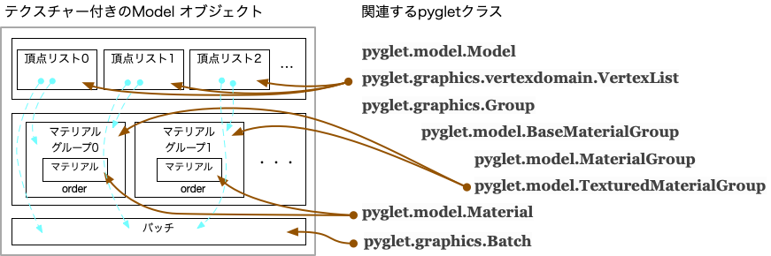
Pygletでの描画プロセスは、BatchとGroupによって交通整理されいる。ひとつのBatchには複数のGroupを関連づけることができて、 各Groupには描画順序を決めるorderという属性を設定できる。orderは整数値で指定し、小さい順に描画が実行される。 そして、各頂点リストには、Batchと共にGroupを指定することができる(上図の水色の破線)。
加えて、MaterialGroupは描画の順序だけでなく、OpenGLの状態の制御にも用いられる。 TexturedMaterialGroupにテクスチャーを設定し、 頂点リストをそのTexturedMaterialGroupと関連づけておくことで、テクスチャーの切り替えを自動化することができる。
この節では、TexturedMaterialGroupを使ってテクスチャー付きの正四面体のModelを生成し、 異なるテクスチャーを貼り付けた正四面体を同時に表示するよう、コードを改修することにする。 テクスチャーのデータとして、レンガ柄に加え、ホルスタイン牛のようなパターンの画像
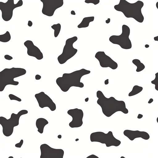
を用意しておいた。
以下はそのコードの例である。
シェーダーの定義まではprog-7-1.pyと全くなので省略してある。
また、変更箇所は ##### で示しておいた。
###
### シェーダーの設定まではprog-7-1.pyと同じ
###

window = pyglet.window.Window(width=1280, height=720, resizable=True)
window.set_caption('Tetrahedron')

batch = pyglet.graphics.Batch()
vert_shader = Shader(vertex_source, 'vertex')
frag_shader = Shader(fragment_source, 'fragment')
shader = ShaderProgram(vert_shader, frag_shader)

holstein = pyglet.image.load('holstein.png')     #####
texture2 = holstein.get_texture()                #####

brick_wall = pyglet.image.load('brick-wall.png') #####
texture1 = brick_wall.get_texture()              #####

time=0
def update(dt):
    global time
    time += dt

@window.event
def on_draw():
    window.clear()
    th_model1.matrix = Mat4.from_rotation(time,Vec3(0,1,0)) @ Mat4.from_rotation(time/3,Vec3(0,0,1)) #####
    th_model2.matrix = Mat4.from_rotation(time,Vec3(1,0,0)) @ Mat4.from_rotation(time/3,Vec3(0,1,0)) #####
    shader['light_position']=Vec3(-5,5,20)
    batch.draw()

@window.event
def on_resize(width, height):
    window.viewport = (0, 0, width, height)
    window.projection = Mat4.perspective_projection(window.aspect_ratio, z_near=0.1, z_far=255, fov=60)
    return pyglet.event.EVENT_HANDLED

def setup():
    glClearColor(0.3, 0.3, 0.5, 1.0)
    glEnable(GL_DEPTH_TEST)
    glEnable(GL_CULL_FACE)
    on_resize(*window.size)

def tetrahedron(shader, texture, batch):  #####
    vpos = [np.array((+1,0,-1/math.sqrt(2))), np.array((-1,0,-1/math.sqrt(2))),
            np.array((0,1,1/math.sqrt(2))), np.array((0,-1,1/math.sqrt(2)))]
    indices = [(0,1,2),(0,3,1),(0,2,3),(1,3,2)]
    normals = []
    vertices = []
    tex_coords = []

    for n in range(4):
        i = indices[n][0]
        j = indices[n][1]
        k = indices[n][2]
        vertices.extend([vpos[i],vpos[j],vpos[k]])
        u = vpos[j] - vpos[i]
        v = vpos[k] - vpos[i]
        n = np.cross(u,v)
        n = n/np.linalg.norm(n)
        normals.extend([n,n,n])
        tex_coords.extend([0, 0, 1, 0, 0.5, math.sqrt(3)/2])

    vertices = np.concatenate(vertices).tolist()
    normals = np.concatenate(normals).tolist()

    diffuse = [1.0, 1.0, 1.0, 1.0]  #####
    ambient = [1.0, 1.0, 0.0, 1.0]  #####
    specular = [1.0, 1.0, 1.0, 1.0] #####
    emission = [0.0, 0.0, 0.0, 1.0] #####
    shininess = 50                  #####

    material = pyglet.model.Material("custom", diffuse, ambient, specular, emission, shininess)    #####
    group = pyglet.model.TexturedMaterialGroup(material=material, program=shader, texture=texture) #####

    vertex_list = shader.vertex_list(len(vertices)//3, GL_TRIANGLES, batch=batch, group=group)     #####
    vertex_list.position[:] = vertices
    vertex_list.normals[:] = normals
    vertex_list.colors[:] = material.diffuse * (len(vertices)//3)
    vertex_list.tex_coords[:] = tex_coords

    return pyglet.model.Model(vertex_lists=[vertex_list], groups=[group], batch=batch) #####

# OpenGLの初期設定
setup()

# 正四面体モデルを生成
th_model1 = tetrahedron(shader,texture1,batch)  #####
th_model2 = tetrahedron(shader,texture2,batch)  #####

# 視点を設定
window.view = Mat4.look_at(position=Vec3(0,0,3), target=Vec3(0,0,0), up=Vec3(0,1,0))

pyglet.clock.schedule_interval(update,1/60)
pyglet.app.run()
prog-7-2.pyの実行画面
prog-7-1.pyからの主な変更点は以下のとおりである。
画像の読み込みとTextureオブジェクトの生成
2つのテクスチャー画像を読み込み、それぞれのテクスチャーをtexture1, texture2に設定する。
holstein = pyglet.image.load('holstein.png')
texture2 = holstein.get_texture()

brick_wall = pyglet.image.load('brick-wall.png')
texture1 = brick_wall.get_texture()
テクスチャー付きのモデルの生成
正四面体を生成している関数 tegrahedron()の後半部を修正し、
Materialクラスのオブジェクトを生成し、使用するテクスチャーを指定しつつ、TexturedMaterialGroupクラスのオブジェクトを生成する。
加えて、pyglet.shader.vertex_list()関数で頂点リストを生成する際に、TexturedMaterialGroupのオブジェクトも指定している。
最後に、pyglet.model.Modelクラスのオブジェクトを生成し、呼び出し側に返している。
diffuse = [1.0, 1.0, 1.0, 1.0]
ambient = [1.0, 1.0, 0.0, 1.0]
specular = [1.0, 1.0, 1.0, 1.0]
emission = [0.0, 0.0, 0.0, 1.0]
shininess = 50

material = pyglet.model.Material("custom", diffuse, ambient, specular, emission, shininess)
group = pyglet.model.TexturedMaterialGroup(material=material, program=shader, texture=texture)

vertex_list = shader.vertex_list(len(vertices)//3, GL_TRIANGLES, batch=batch, group=group)
vertex_list.position[:] = vertices
vertex_list.normals[:] = normals
vertex_list.colors[:] = material.diffuse * (len(vertices)//3)
vertex_list.tex_coords[:] = tex_coords

return pyglet.model.Model(vertex_lists=[vertex_list], groups=[group], batch=batch)
この例でMaterialのコンストラクターに多くのパラメーターを渡しているが、実際に描画に使用しているのはdiffuseのみである。
そして、プログラムの最後のあたりで
th_model1 = tetrahedron(shader,texture1,batch)
th_model2 = tetrahedron(shader,texture2,batch)
によって、テクスチャーだけ異なる2つの正四面体モデルのオブジェクトを生成している。
モデル変換行列の更新
Modelクラスのオブジェクトは、matrixというインスタンス変数を参照して、シェーダーのuniform変数modelの更新を行うように設計されている。
そのため、モデル行列を更新する際には、シェーダープログラム['model']にアクセスするのではなく、
モデルオブジェクト.matrix = 行列で設定すればよい。
prog-7-2.pyでは on_draw()関数の中で、
th_model1.matrix = Mat4.from_rotation(time,Vec3(0,1,0)) @ Mat4.from_rotation(time/3,Vec3(0,0,1))
th_model2.matrix = Mat4.from_rotation(time,Vec3(1,0,0)) @ Mat4.from_rotation(time/3,Vec3(0,1,0))
によって、それぞれのオブジェクトに異なるモデル行列を設定している。
7.3 複数のテクスチャーの読み込みと法線マッピング
ここでは複数のテクスチャー情報を「合成」して質感を表現する例として、法線マップの実装例を紹介する。
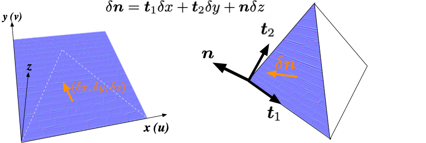
物体の形状は、基本的に頂点座標で表すことになるが、表面の細かな凹凸まで表現しようとすると、膨大な数のポリゴンが必要となって効率的でない。 そこで、表面の凹凸に起因する法線のずれ(ゆらぎ)成分を伴ったベクトル情報をテクスチャー画像として別途用意しておいて、 ポリゴンの法線ベクトル $\boldsymbol{n}$ の代わりに、ずれ成分を伴った$\delta \boldsymbol{n}$ によって 陰影を計算することで、よりリアルな表現を行おうというのが法線マッピング(normal mapping)の手法である。
ブロック壁の画像をもとに、法線情報を画像化したものが以下である:
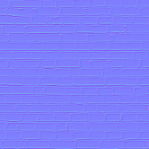
法線のx成分をR, y成分をG, z成分をBに対応させている。 xがテクスチャー画像のu、yがvに相当しているので、この座標系では凹凸のない面の法線ベクトルは(0,0,1)となる。 ベクトルの成分は負の値も取り得る一方いで、画素値は0から1の値して取れないので、 画素値(0.5,0.5,0.5)をベクトル(0,0,0)に対応づけるように下駄を履かせる慣習になっている。 従って、ゆらぎの全くない場合の色は (0.5, 0.5, 1.0) となり、これは矢車菊色である。
物体表面に陰影をつけるためには、 テクスチャー座標系、すなわちu、v、そして高さ方向に対応した基底ベクトルが、ビュー座標系にどのように変換されるかを求める必要がある。 そのためには、法線に加え、uとvに対応した面の接ベクトル $\boldsymbol{t}_1$, $\boldsymbol{t}_2$ を頂点リストとしてシェーダーに与える必要がある。 ただし、この例では角度が不変であるようなモデルビュー変換(回転、等方的な拡大・縮小、移動)しか行っていないので、 接ベクトルのひとつは、$ \boldsymbol{t}_2 = \boldsymbol{n} \times \boldsymbol{t}_1$ のようにして求めることができる。 そのため、この場合、頂点リストに加えるのは一方($\boldsymbol{t}_1$)のみでも十分である。
こうして、ビュー座標系での基底ベクトル $\boldsymbol{t}_1, \boldsymbol{t}_2, \boldsymbol{n}$ が求まれば、 下図のとおり、ビュー座標系での $\delta \boldsymbol{n}$ を計算できる。
以上のアイデアをもとに、法線マッピングを行うよう、prog-7-1.pyのシェーダー、およびプログラム本体を修正したコードの例を以下に示す。
おもな変更箇所は ##### で示しておいた。
import numpy as np
import math
import pyglet
from pyglet.gl import *
from pyglet.math import Mat4, Vec3
from pyglet.graphics.shader import Shader, ShaderProgram

# シェーダー
# Vertex shader
vertex_source = """#version 330 core
    in vec3 position;
    in vec3 normals;
    in vec3 tangents;    #####
    in vec4 colors;
    in vec2 tex_coords;

    out vec4 vertex_colors;
    out vec3 vertex_normals;
    out vec3 vertex_tangents;  #####
    out vec3 vertex_position;
    out vec2 texture_coords;

    uniform WindowBlock
    {
        mat4 projection;
        mat4 view;
    } window;

    uniform mat4 model;

    void main()
    {
        mat4 modelview = window.view * model;
        vec4 pos = modelview * vec4(position, 1.0);
        gl_Position = window.projection * pos;
        mat3 normal_matrix = transpose(inverse(mat3(modelview)));
        vertex_position = pos.xyz;
        vertex_colors = colors;
        vertex_normals = normal_matrix * normals;
        vertex_tangents = normal_matrix * tangents;  #####
        texture_coords = tex_coords;
    }
"""

fragment_source = """#version 330 core
    in vec4 vertex_colors;
    in vec3 vertex_normals;
    in vec3 vertex_tangents;  #####
    in vec3 vertex_position;
    in vec2 texture_coords;
    out vec4 final_colors;

    uniform vec3 light_position;
    uniform sampler2D texture_0;  #####
    uniform sampler2D texture_1;  #####

    void main()
    {
        vec3 normal = normalize(vertex_normals);
        vec3 bitangent = normalize(cross(normal, normalize(vertex_tangents)));      #####
        mat3 tbn_mat = mat3(vertex_tangents, bitangent, normal);                    #####
        vec3 tex_normal = normalize(texture(texture_1, texture_coords).xyz - 0.5) ; #####
        vec3 delta_normal = tbn_mat * tex_normal;                                   #####
        vec3 light_dir = normalize(light_position - vertex_position);
        float diff = max(dot(delta_normal, light_dir), 0.0);               #####
        final_colors = (texture(texture_0, texture_coords) * vertex_colors) * diff; #####
    }
"""

class TwoTexturedMaterialGroup(pyglet.model.TexturedMaterialGroup):  #####
    def __init__(self, material: pyglet.model.Material, program: pyglet.graphics.shader.ShaderProgram, \
                 texture0: pyglet.image.Texture, texture1: pyglet.image.Texture, \
                 order: int = 0, parent: pyglet.graphics.Group | None = None):
        super().__init__(material, program, texture0, order, parent)
        self.texture0 = texture0
        self.texture1 = texture1

    def set_state(self) -> None:
        self.program['texture_0'] = 0
        glActiveTexture(GL_TEXTURE0)
        glBindTexture(self.texture0.target, self.texture0.id)
        self.program['texture_1'] = 1
        glActiveTexture(GL_TEXTURE1)
        glBindTexture(self.texture1.target, self.texture1.id)
        self.program.use()
        self.program['model'] = self.matrix

    def __hash__(self) -> int:
        return hash((self.texture0.target, self.texture0.id, self.program, self.order, self.parent))

    def __eq__(self, other) -> bool:
        return (self.__class__ is other.__class__ and
                self.material == other.material and
                self.matrix == other.matrix and
                self.texture.target == other.texture.target and
                self.texture.id == other.texture.id and
                self.program == other.program and
                self.order == other.order and
                self.parent == other.parent)

window = pyglet.window.Window(width=1280, height=720, resizable=True)
window.set_caption('Tetrahedron')

batch = pyglet.graphics.Batch()
vert_shader = Shader(vertex_source, 'vertex')
frag_shader = Shader(fragment_source, 'fragment')
shader = ShaderProgram(vert_shader, frag_shader)

brick_wall = pyglet.image.load('brick-wall.png')           #####
texture0 = brick_wall.get_texture()                        #####

normalmap = pyglet.image.load('brick-wall-normalmap.png')  #####
texture1 = normalmap.get_texture()                         #####

time=0
def update(dt):
    global time
    time += dt

@window.event
def on_draw():
    window.clear()
    th_model.matrix = Mat4.from_rotation(time,Vec3(1,0,0)) @ Mat4.from_rotation(time/3,Vec3(0,1,0))
    shader['light_position']=Vec3(-5,5,20)
    batch.draw()

@window.event
def on_resize(width, height):
    window.viewport = (0, 0, width, height)
    window.projection = Mat4.perspective_projection(window.aspect_ratio, z_near=0.1, z_far=255, fov=60)
    return pyglet.event.EVENT_HANDLED

def setup():
    glClearColor(0.3, 0.3, 0.5, 1.0)
    glEnable(GL_DEPTH_TEST)
    glEnable(GL_CULL_FACE)
    on_resize(*window.size)

def tetrahedron(shader, texture0, texture1, batch):
    vpos = [np.array((+1,0,-1/math.sqrt(2))), np.array((-1,0,-1/math.sqrt(2))),
            np.array((0,1,1/math.sqrt(2))), np.array((0,-1,1/math.sqrt(2)))]
    indices = [(0,1,2),(0,3,1),(0,2,3),(1,3,2)]
    normals = []
    tangents = []      #####
    vertices = []
    tex_coords = []

    for n in range(4):
        i = indices[n][0]
        j = indices[n][1]
        k = indices[n][2]
        vertices.extend([vpos[i],vpos[j],vpos[k]])
        tangents.extend([vpos[j]-vpos[i], vpos[j]-vpos[i], vpos[j]-vpos[i]])  #####
        u = vpos[j] - vpos[i]
        v = vpos[k] - vpos[i]
        n = np.cross(u,v)
        n = n/np.linalg.norm(n)
        normals.extend([n,n,n])
        tex_coords.extend([0, 0, 1, 0, 0.5, math.sqrt(3)/2])

    vertices = np.concatenate(vertices).tolist()
    normals = np.concatenate(normals).tolist()
    tangents = np.concatenate(tangents).tolist()    #####

    diffuse = [1.0, 1.0, 1.0, 1.0]
    ambient = [1.0, 1.0, 0.0, 1.0]
    specular = [1.0, 1.0, 1.0, 1.0]
    emission = [0.0, 0.0, 0.0, 1.0]
    shininess = 50

    material = pyglet.model.codecs.base.SimpleMaterial("custom", diffuse, ambient, specular, emission, shininess)
    group = TwoTexturedMaterialGroup(material=material, program=shader, \
                                     texture0=texture0, texture1=texture1)

    vertex_list = shader.vertex_list(len(vertices)//3, GL_TRIANGLES, batch=batch, group=group)
    vertex_list.position[:] = vertices
    vertex_list.normals[:] = normals
    vertex_list.tangents[:] = tangents  #####
    vertex_list.colors[:] = material.diffuse * (len(vertices)//3)
    vertex_list.tex_coords[:] = tex_coords

    return pyglet.model.Model(vertex_lists=[vertex_list], groups=[group], batch=batch)

# OpenGLの初期設定
setup()

# 正四面体モデルを生成
th_model = tetrahedron(shader,texture0,texture1,batch)

# 視点を設定
window.view = Mat4.look_at(position=Vec3(0,0,3), target=Vec3(0,0,0), up=Vec3(0,1,0))

pyglet.clock.schedule_interval(update,1/60)
pyglet.app.run()
prog-7-3.pyのスナップショット
prog-7-3.pyでは、二種類のテクスチャーを使用するために、TexturedMaterialGroupのサブクラスTwoTexturedMaterialGroupを設け、
set_state()メソッドの中で必要な処理を行っている。
この例のように、複数のテクスチャーを用いる場合は Groupクラスのサブクラスを定義しておき、set_state()メソッドの中で
self.program['uniform変数名0'] = 0
glActiveTexture(GL_TEXTURE0 + 0)
glBindTexture(texture0.target, texture0.id)

self.program['uniform変数名1'] = 1
glActiveTexture(GL_TEXTURE0 + 1)
glBindTexture(texture1.target, texture1.id)

self.program['uniform変数名1'] = 2
glActiveTexture(GL_TEXTURE0 + 2)
glBindTexture(texture2.target, texture2.id)
...
glEnable(GL_BLEND)
glBlendFunc(Blendソースモード, Blendデスティネーションモード)
のようなコードでテクスチャー情報を設定し、
pyglet.graphics.shader.ShaderProgram.vertex_list() を呼び出す際の引数(group)に登録しておくと、Pygletが自動的に処理してくれる。
8. 物理モデルによる質感表現
8.1 散乱、鏡面反射、環境光、そして放出光の効果
OpenGLでは、物理モデルに基づいた物体表面の質感表現として、散乱(diffuse)、鏡面反射(specular)、環境光(ambient)、そして放出光(emission)が古くから用いられてきた。 以下に、その内容とシェーダーを使った表現方法について述べる。
表面からの乱反射
遠方の光源から平行な光線が平面に入射し、それが面でロス無く全て反射される状況を考えてみよう。 ただし、面の表面はザラザラしていて、入射光はあちらこちらに向きを変えながら一様に散乱(乱反射)されると考える。 面の法線ベクトルと入射光との成す角度を$\theta$とすると、断面積$A$の入射光は、面上の面積 $A /\cos \theta$ を照らすことになる。 断面積あたりの光のエネルギー量を$E$、面上から面積あたり放出されるエネルギー量を$E'$とすると、いま入射エネルギーと放出エネルギーが等しい(エネルギーは保存する)と考えているので、 $$ E A = E' \frac{A}{\cos \theta} $$ すなわち $$ E' = E \cos \theta $$ となる。もし散乱の過程でロスが生じる場合であっても、面から散乱される光量が$\cos \theta$に依存することには変わりはないだろう。
単位法線ベクトルを$\boldsymbol{n}$、照らされている面上の点から光源方向の単位ベクトルを$\boldsymbol{\ell}$とすると、
$$
\cos \theta = \boldsymbol{n} \cdot \boldsymbol{\ell}
$$
であるから、フラグメント・シェーダーで $\boldsymbol{n}$ を変数normal、
$\boldsymbol{\ell}$ を変数light_dirで表し、
内積を与える組み込み関数dot()を使うことで、
面からの散乱光の強さは以下のコードで計算できる。
vec3 normal = normalize(vertex_normals);
vec3 light_dir = normalize(light_position - vertex_position);
float diff = max(dot(normal, light_dir), 0.0);
final_colors = vertex_diffuse * diff;
ここで、normalize()は、ベクトルを単位ベクトルに規格化する組み込み関数である。
また、光線が面の「裏側」から到来する場合、当然、散乱光は生じないので、上のコードでは、組み込みのmax()関数を使って、
内積の値が負の場合は光量を0にするようになっている。
散乱の程度は色(波長)によっても異なるので、色毎の散乱強度を変数vertex_diffuseで表し、それに方向因子diffを乗じて、
最終的な色final_colorとしている。
表面からの鏡面反射
表面が鏡面の場合は、入射方向によって出射方向が一意に決まることになる。 表面上のある点から光線源への方向を単位ベクトル $\boldsymbol{\ell}$ で表すことにしよう。 そのとき、入射ベクトルを $\boldsymbol{\alpha} = -\boldsymbol{\ell}$とする。 また、面の法線(単位ベクトル)を $\boldsymbol{n}$とすると、 出射ベクトル $\boldsymbol{\beta}$ は $$ \boldsymbol{\beta} = \boldsymbol{\alpha} - 2 (\boldsymbol{\alpha} \cdot \boldsymbol{n}) \boldsymbol{n} $$ で与えられる(面の法線方向の「運動量」が反転する)。$\boldsymbol{\ell}$で表せば $$ \boldsymbol{\beta} = - \boldsymbol{\ell} + 2 (\boldsymbol{\ell} \cdot \boldsymbol{n}) \boldsymbol{n} $$ である。
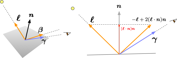
もし、$\boldsymbol{\beta}$が視点(カメラ)の方向$\boldsymbol{\gamma}$に完全に一致すれば、カメラには光源の光が映り込むはずである。 実際には、2つの方向が完全に一致するチャンスはほとんど無いだろうから、方向の「近さ」に応じて、光量を調整するのが良さそうだ。 そこで、余弦のべき乗関数 $$ \left(\boldsymbol{\beta} \cdot \boldsymbol{\gamma} \right)^\sigma $$ によって、視点での反射の強さを表現することにする。$\sigma (\ge 0)$が大きいほど、反射は「スポット状」に近くなる。
光源の方向 $\boldsymbol{\ell}$を変数light_dir, 反射光の方向ベクトル $\boldsymbol{\beta}$ をrefrect_dir、反射点からの視点の方向 $\boldsymbol{\gamma}$ を変数 view_dir,
そして、べき指数$\sigma$をvertex_shininessで表すことにすると、鏡面反射の効果はフラグメントシェーダーを使って次のように記述できるだろう。
vec3 normal = normalize(vertex_normals);
vec3 light_dir = normalize(light_position - vertex_position);
vec3 refrect_dir = normalize(-light_dir + 2 * dot(light_dir, normal) * normal);
vec3 view_dir = -normalize(vertex_position);
float spec = pow(max(dot(view_dir, refrect_dir), 0.0), vertex_shininess);
final_colors = vertex_specular * spec * light_color;
ここで、vertex_specularは鏡面反射の際の各色の反射割合, light_colorは光源の色がセットされている変数である。
pow()はべき乗を計算する組み込み関数である。
裏面からの光は視点には届かないので、max()組み込み関数を使って、内積が0以下の場合は輝度を0に設定している
(併せて、べき乗関数の引数が0以上の値になることを保証する)。
なお、GLSLの組み込み関数 reflect()を用いると、反射光の方向計算のところは
vec3 refrect_dir = reflect(-light_dir,normal);
と書くこともできる。
環境光の効果
空間全体が間接照明されている(環境光で満たされている)場合は、全ての面から、照明の色と物体表面の色に応じた光が放出されるはずである。
フラグメントシェーダーでこの効果を表現するには、間接照明時の物体の表面色vertex_ambientと、
照明色 light_color を使って、
final_colors = vertex_ambient * light_color;
と表現できる。
放出光の効果
物体表面それ自体が(例えば、スマートフォンのスクリーンのように)光を放っている場合は、ライティングとは関係なく、物体表面が輝度を持つ。
発光色と強度を変数vertex_emissionで表すとき、フラグメントシェーダーでこの効果は
final_colors = vertex_emission ;
と表現できるだろう。
8.2 黄金に光る正四面体
以上の4つの効果を全て考慮し、フラグメントシェーダーの出力部を
final_colors = vertex_ambient * light_color + vertex_diffuse * diff + vertex_specular * spec * light_color + vertex_emission ;
として、金色の光沢を持った正四面体を表現してみたコードの例を以下に示す。
import numpy as np
import math
import pyglet
from pyglet.gl import *
from pyglet.math import Mat4, Vec3, Vec4
from pyglet.graphics.shader import Shader, ShaderProgram
# シェーダー
# Vertex shader
vertex_source = """#version 330 core
in vec3 position;
in vec3 normals;
in vec4 diffuse_colors;
in vec4 ambient_colors;
in vec4 specular_colors;
in vec4 emission_colors;
in float shininess;
out vec4 vertex_diffuse;
out vec4 vertex_ambient;
out vec4 vertex_specular;
out vec4 vertex_emission;
out float vertex_shininess;
out vec3 vertex_normals;
out vec3 vertex_position;
uniform WindowBlock
{
mat4 projection;
mat4 view;
} window;
uniform mat4 model;
void main()
{
mat4 modelview = window.view * model;
vec4 pos = modelview * vec4(position, 1.0);
gl_Position = window.projection * pos;
mat3 normal_matrix = transpose(inverse(mat3(modelview)));
vertex_position = pos.xyz;
vertex_diffuse = diffuse_colors;
vertex_ambient = ambient_colors;
vertex_specular = specular_colors;
vertex_emission = emission_colors;
vertex_shininess = shininess;
vertex_normals = normal_matrix * normals;
}
"""
fragment_source = """#version 330 core
in vec4 vertex_diffuse;
in vec4 vertex_ambient;
in vec4 vertex_specular;
in vec4 vertex_emission;
in float vertex_shininess;
in vec3 vertex_normals;
in vec3 vertex_position;
out vec4 final_colors;
uniform vec3 light_position;
uniform vec4 light_color;
void main()
{
vec3 normal = normalize(vertex_normals);
vec3 light_dir = normalize(light_position - vertex_position);
vec3 refrect_dir = normalize(-light_dir + 2 * dot(light_dir, normal) * normal);
// vec3 refrect_dir = reflect(-light_dir, normal);
vec3 view_dir = -normalize(vertex_position);
float spec = pow(max(dot(view_dir, refrect_dir), 0.0), vertex_shininess);
float diff = max(dot(normal, light_dir), 0.0);
final_colors = vertex_ambient * light_color
+ vertex_diffuse * diff
+ vertex_specular * spec * light_color
+ vertex_emission ;
}
"""
class MyMaterialGroup(pyglet.model.BaseMaterialGroup):
def __init__(self, material:pyglet.model.Material, program: pyglet.graphics.shader.ShaderProgram, \
order:int=0, parent: pyglet.graphics.Group | None = None):
super().__init__(material, program, order, parent)
def set_state(self) -> None:
self.program.use()
self.program['model'] = self.matrix
def __hash__(self) -> int:
return hash((self.program, self.order, self.parent))
def __eq__(self, other) -> bool:
return (self.__class__ is other.__class__ and
self.material == other.material and
self.matrix == other.matrix and
self.program == other.program and
self.order == other.order and
self.parent == other.parent)
window = pyglet.window.Window(width=1280, height=720, resizable=True)
window.set_caption('Tetrahedron')
batch = pyglet.graphics.Batch()
vert_shader = Shader(vertex_source, 'vertex')
frag_shader = Shader(fragment_source, 'fragment')
shader = ShaderProgram(vert_shader, frag_shader)
time=0
def update(dt):
global time
time += dt*0.5
@window.event
def on_draw():
window.clear()
th_model.matrix = Mat4.from_rotation(time,Vec3(0,1,0)) @ Mat4.from_rotation(time/2,Vec3(0,0,1)) @ Mat4.from_rotation(time/3,Vec3(1,0,0))
shader['light_position']=Vec3(-200,100,200)
shader['light_color']=Vec4(1.0, 1.0, 1.0, 1.0)
batch.draw()
@window.event
def on_resize(width, height):
window.viewport = (0, 0, width, height)
window.projection = Mat4.perspective_projection(window.aspect_ratio, z_near=0.1, z_far=255, fov=60)
return pyglet.event.EVENT_HANDLED
def setup():
glClearColor(0.3, 0.3, 0.5, 1.0)
glEnable(GL_DEPTH_TEST)
glEnable(GL_CULL_FACE)
on_resize(*window.size)
def tetrahedron(shader, diffuse, ambient, specular, emission, shininess, batch):
vpos = [np.array((+1,0,-1/math.sqrt(2))), np.array((-1,0,-1/math.sqrt(2))),
np.array((0,1,1/math.sqrt(2))), np.array((0,-1,1/math.sqrt(2)))]
indices = [(0,1,2),(0,3,1),(0,2,3),(1,3,2)]
normals = []
vertices = []
for n in range(4):
i = indices[n][0]
j = indices[n][1]
k = indices[n][2]
vertices.extend([vpos[i],vpos[j],vpos[k]])
u = vpos[j] - vpos[i]
v = vpos[k] - vpos[i]
n = np.cross(u,v)
n = n/np.linalg.norm(n)
normals.extend([n,n,n])
vertices = np.concatenate(vertices).tolist()
normals = np.concatenate(normals).tolist()
material = pyglet.model.codecs.base.SimpleMaterial("custom", diffuse, ambient, specular, emission, shininess)
group = MyMaterialGroup(material=material, program=shader)
vertex_list = shader.vertex_list(len(vertices)//3, GL_TRIANGLES, batch=batch, group=group)
vertex_list.position[:] = vertices
vertex_list.normals[:] = normals
vertex_list.diffuse_colors[:] = material.diffuse * (len(vertices)//3)
vertex_list.ambient_colors[:] = material.ambient * (len(vertices)//3)
vertex_list.specular_colors[:] = material.specular * (len(vertices)//3)
vertex_list.emission_colors[:] = material.emission * (len(vertices)//3)
vertex_list.shininess[:] = [material.shininess] * (len(vertices)//3)
return pyglet.model.Model(vertex_lists=[vertex_list], groups=[group], batch=batch)
# OpenGLの初期設定
setup()
# 正四面体モデルを生成
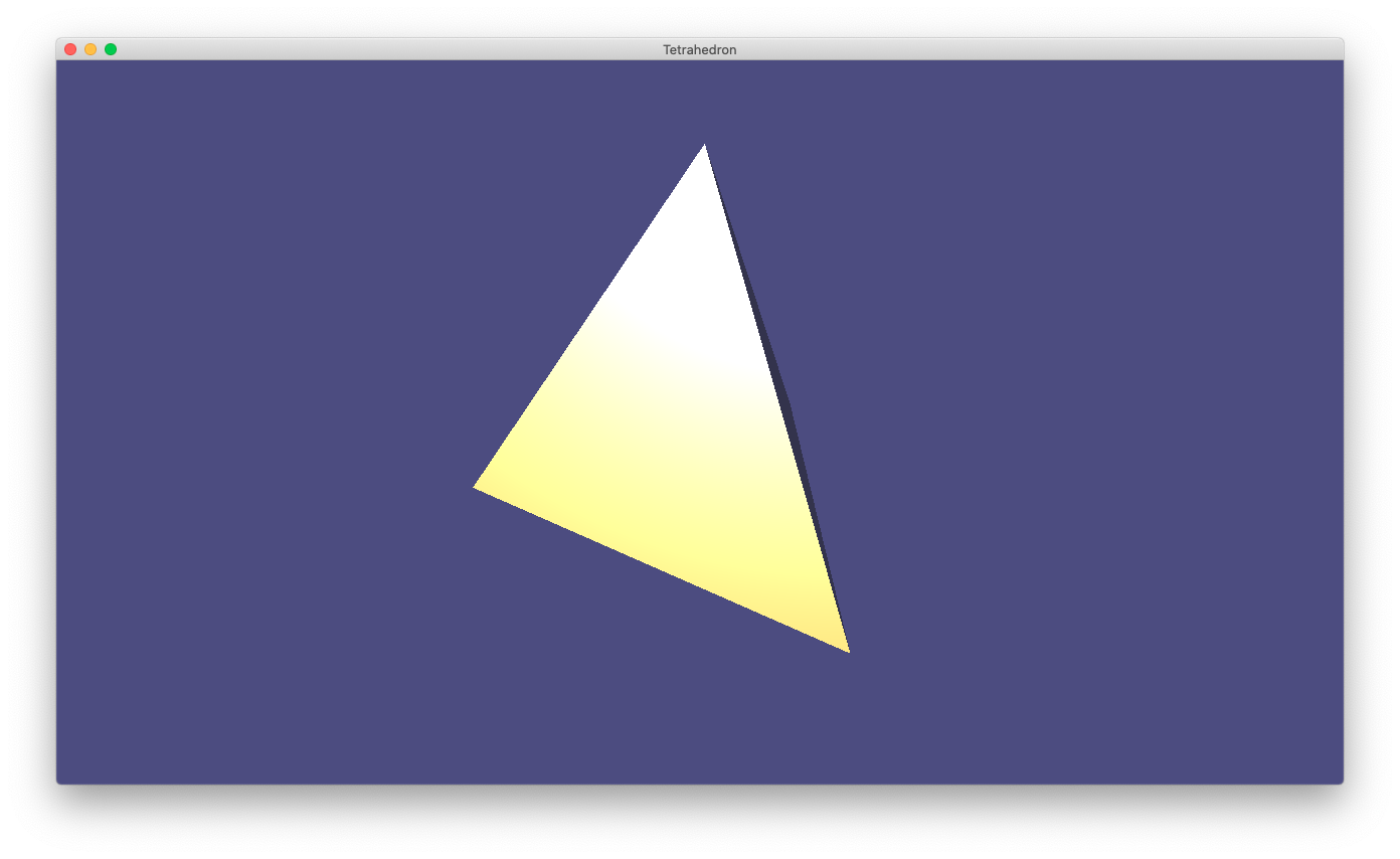
th_model = tetrahedron(shader=shader,diffuse=[0.9,0.7,0.13,1], ambient=[0.1,0.1,0.2,1], specular=[1,1,1,1], emission=[0.1,0.1,0.1,1],shininess=5,batch=batch)
# 視点を設定
window.view = Mat4.look_at(position=Vec3(0,0,3), target=Vec3(0,0,0), up=Vec3(0,1,0))
pyglet.clock.schedule_interval(update,1/60)
pyglet.app.run()
prog-8-2.pyを実行中のスナップショット
このコードでは、頂点シェーダーで、散乱色(diffuse_colors)以外に、鏡面反射(specular_colors)の色と光具合(shininess)、環境光の色(ambient_colors)、発光色(emission_colors)を頂点リストから入力して、そのままフラグメントシェーダーに渡している。 そして、フラグメントシェーダーでは、上で説明した計算方法によって、各点の色を算出している。
prog-8-2.pyは、上記の表面の処理以外はほぼprog-7-2.pyと同様であるが、
テクスチャーは使わず、従って、tetorahedron()関数の中で物体のモデルを作成する際に、
(pyglet.model.TexturedMaterialGroupではなく) pyglet.model.MaterialGroupを用いている点が異なっている。
グループを生成する際に、Pygletに内蔵の MaterialGroupクラスはオブジェクトの同値性のチェックが実装されていなかったため、
MyMaterialGroupを新たに定義し用いている。
これまでに登場した手法を組み合わせ、例題プログラム prog-4-2.py を「上下方向」にも拡張し、シェルピンスキーのピラミッドと呼ばれるフラクタルパターンを描画した例を示す。
注目するスケールを1/2倍すると、正四面体が4つ現れることから、このパターンのフラクタル次元$D$は $$ D = - \frac{\log 4}{\log(1/2)} = 2 $$ となり、平面の次元と同じになる。 ちょっと考えると、上に乗っている正四面体を引っくり返して回転すると、ちょうど下の窪みにはまることがわかる。 それを繰り返すと、下側の面が隙間なく埋まることから、正四面体のサイズが無限小になった極限では、平面と同じ「体積」となるわけだ。
(このあたりから先はこれから)